
This is a very interesting build. If I were to make it again, I would go for a dual detector and the fast ADC, but even with its slow measuring rate (7 measurements per second), it’s still a very interesting piece of equipment to have. It can be used to measure complex impedances of all kinds of circuits. Using a bridge (I still have to build mine), you can also check antennas, something I’m looking forward to measure. You can find N2PK’s project page for this instrument here.
At the heart of the VNA is a dual DDS (direct digital synthesis, a digital sine-wave generator), clocked with the same oscillator. This allows you to generate two sine waves of the same frequency, and set the phase offset between the two signals yourself. One signal goes to a mixer, the other signal passes through a device under test, and then arrives at the mixer. Then it’s simply a matter of measuring the DC output at multiple phases, and from that you can calculate magnitude and angle of your signal. When properly calibrated, the software can calculate the effect of the device under test.
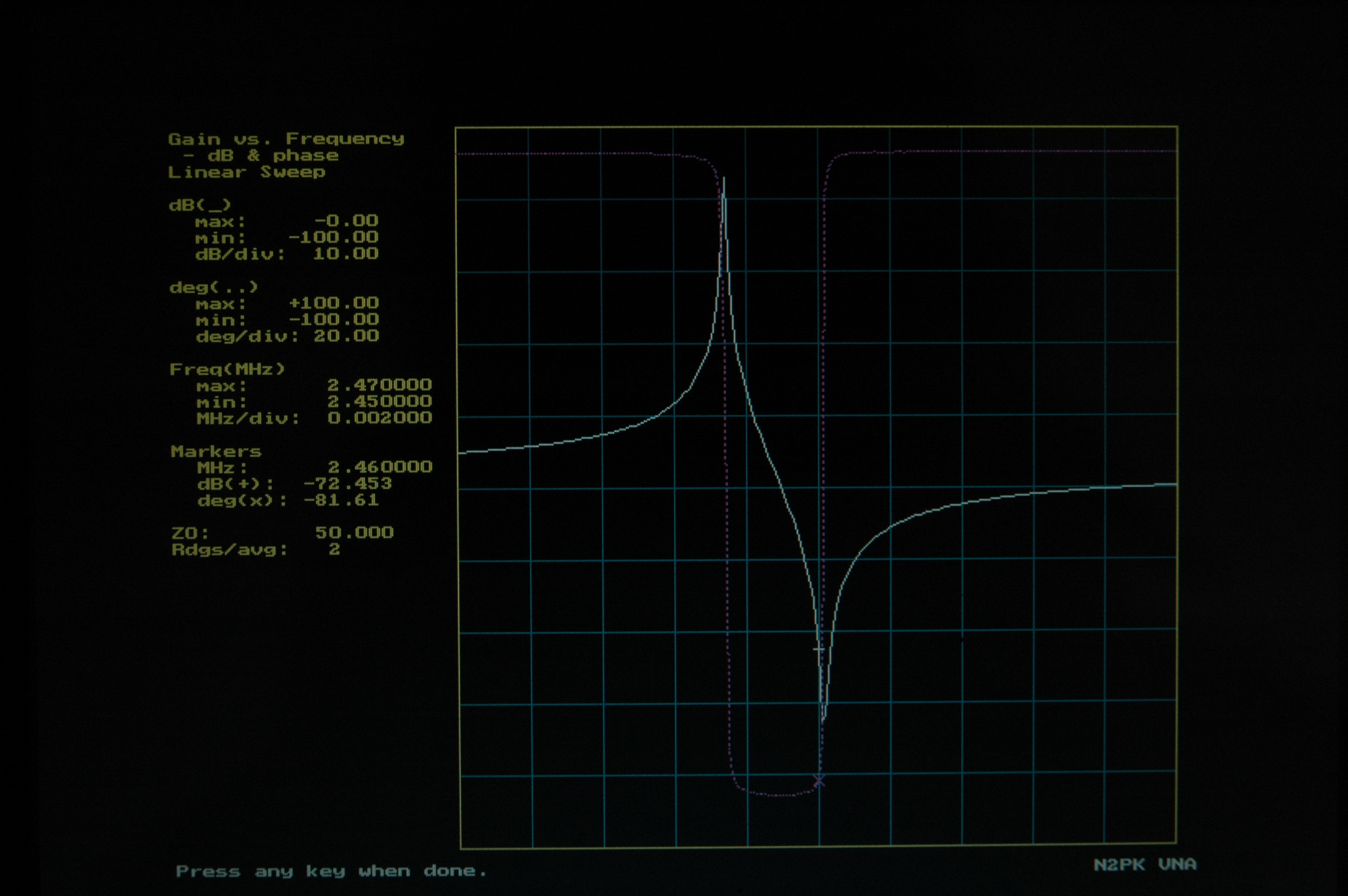
The full line is the magnitude, the dotted line is the phase.
The first measurement I made was of a crystal oscillator. I connected the crystal between output and input, and did a sweep around the frequency of the crystal. The result shows a sharp rise in magnitude, and then the signal goes down, but instead of returning to its original value, it keeps going down until it reaches a negative peak. What is that? Well, a crystal has both a series resonant frequency (low impedance, band-pass) and a parallel resonant frequency (high impedance, band notch). What you see here are these two frequencies. To quote the Wikipedia article: “A quartz crystal provides both series and parallel resonance. The series resonance is a few kilohertz lower than the parallel one”. Theory and measurement match perfectly. Another thing to notice is the purple dotted line: it shows the phase of the signal. You can see that the phase changes 180° between the resonant points. This is also what you will find in text books, between these two points it behaves inductively. So with this simple first measurement, we have already learned a lot about crystals.
This is the first project where I had to source all the components myself. It went smoother than expected, actually. The only “problem” was selecting the master oscillator and the dual flip-flop. I used the 156.25 MHz option. The problem is that it’s a 3.3V module, while the original design calls for a 5V module. You can use a capacitor and a dual resistor voltage divider to provide the clock to the flip-flop, but it’s not really clean and it only works if you have a CMOS-level flip-flop. As the original flip-flop was unavailable, I had taken a replacement with a TTL input level. Not wanting to mess around, I made a small PCB with a 3.3V voltage regulator and a fast TTL level not-gate, both in SOT23-5 packages. The regulator provides the 3.3V, and the not-gate acts as a 3.3V to 5V output convertor (inverting, but for a clock that’s not a problem).