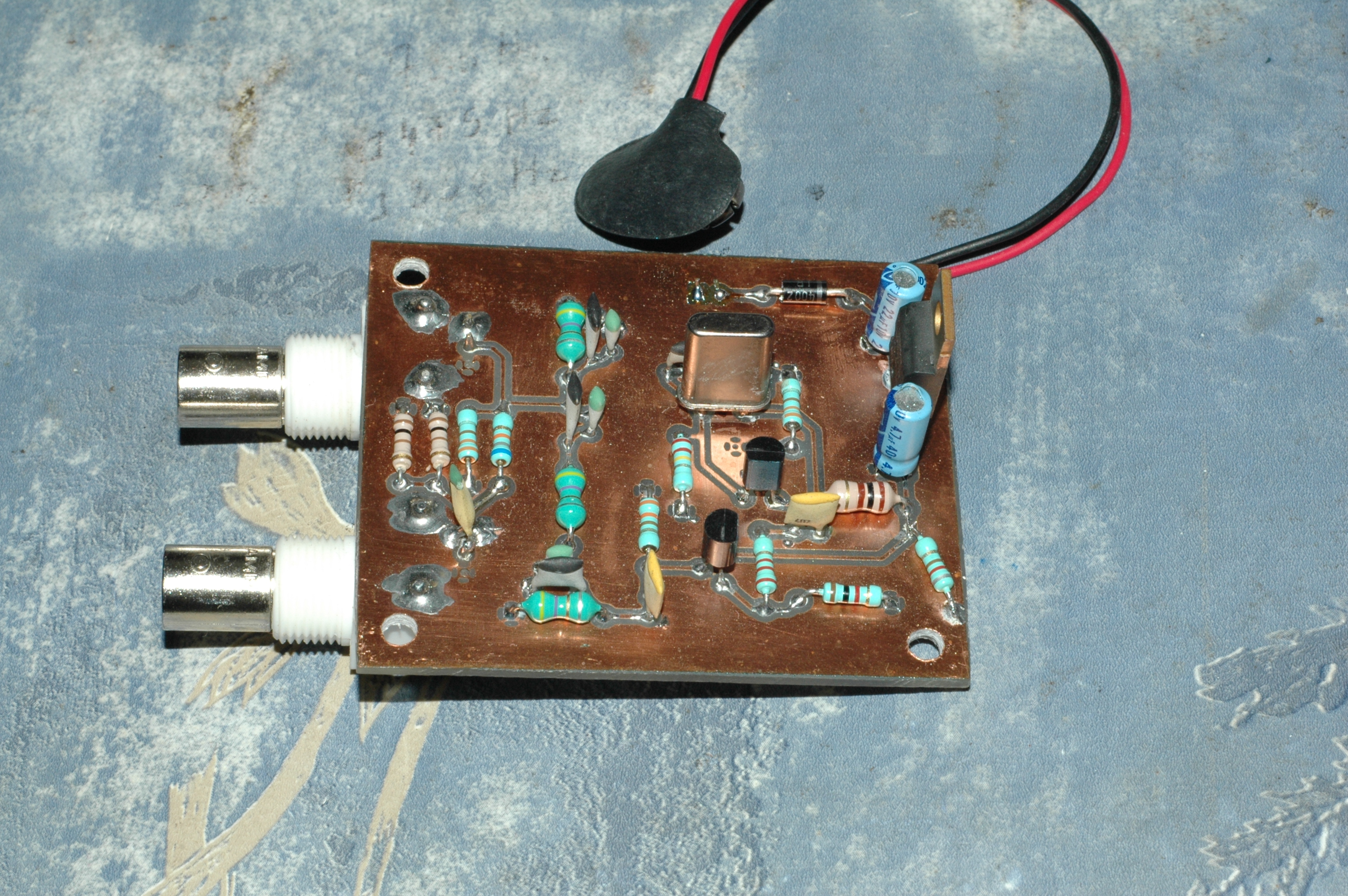
Update: There used to be an error in the schematic, R2 was missing. It is needed to work correctly.
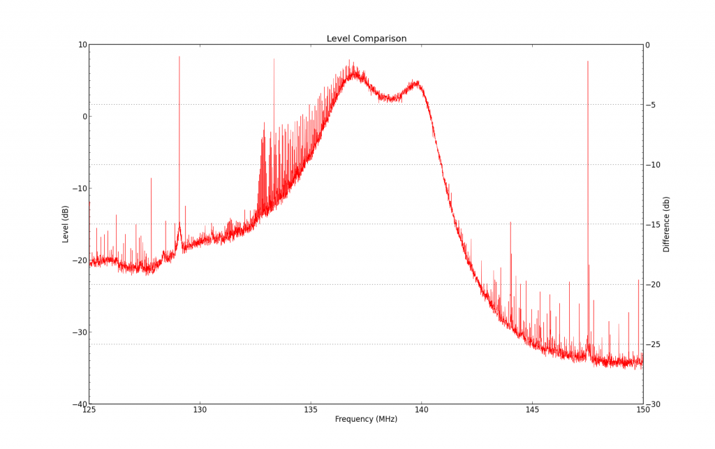
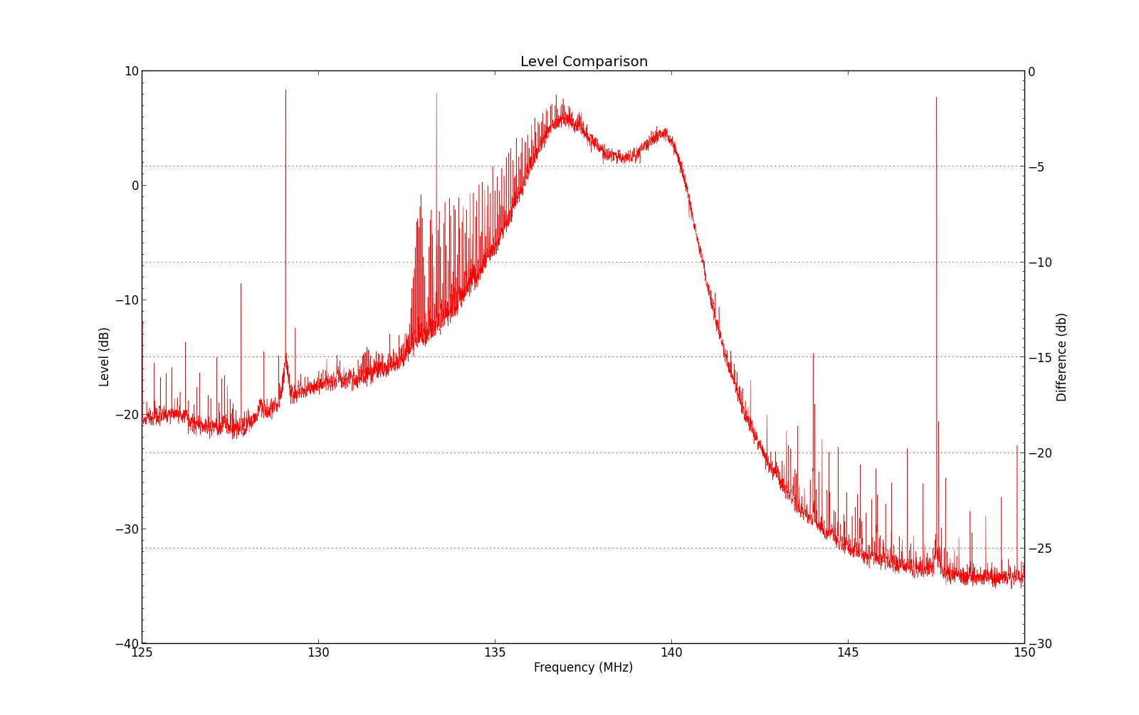
Frequency response of the 137MHz filter (don’t mind the spurs)
If you want to see the frequency response of a filter, a spectrum analyzer with a tracking generator will be the tool of the trade. There’s only one problem: I don’t have one. An alternative is to hook up an RF signal generator, measure the output power of the filter with a power meter at multiple frequencies, and plot the result manually. But here too I have a problem: I don’t have a signal generator. Or a power meter. Besides, it’s a lot of work. So when I wanted to test a 137MHz bandpass filter, at first I didn’t think it would be possible. Fortunately I found a way that works reasonably well, and cost me nothing.
Using an RTL-SDR dongle, you can sample a piece of the spectrum up to 2 or 3MHz wide at a time. That’s not really enough for use as a spectrum analyzer. However, what you can do is to make the dongle hop from one frequency to the next, and make a composite spectrum. There is software that does just that: rtlsdr-scanner. This is fine if you want to scan the bands to spot interesting frequencies, but I still can’t measure filters with it.
If only I had a transmitter that transmits at every frequency: I could pass it through the filter and see what remains at the other side! Something like a wideband noise generator. After asking Google, it turns out that generating such noise is quite easy: a diode, when operating at the reverse breakdown voltage, generates a fair amount of noise, hundreds of megahertz wide! Then it’s just a matter of blocking the DC voltage with a capacitor, and there you have it, you are now the proud owner of a noise source! You then send this noise through an amplifier stage, but I used the amplifier of the dongle instead (I can set the gain between -1 and +42dB). Not ideal, because there are lots of other signals picked up too, but changing a slider in software is much less work than making a wideband amplifier. I also added an extenal 6dB attenuator immediately after the noise source to get better impedance matching to 50Ω.
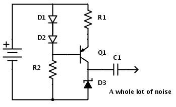
A current source (D1, D2, R1 and Q1) feeding a zener diode. Any diode will do really, just make sure the breakdown voltage is reached. R1 determines the current (there’s a 0.6V drop over the resistor so i=V/R).
R2 value is not critical, 10k-100k is fine.
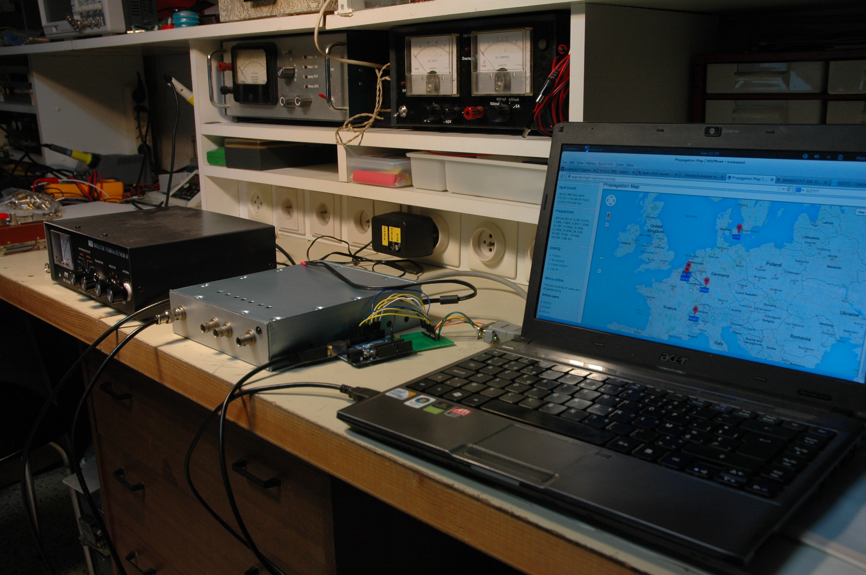
The setup is now ready for prime time. When I turn on the noise generator, the noise floor of the dongle increases by 30dB around 130MHz. So far so good. I set the start- and stopfrequencies to 125MHz and 150MHz, and do a sweep. I repeat the measurement with the filter in between, and save both sweeps. Then in Tools->Compare, I can subtract the two signals. This sets the noise level as the 0dB reference. The result is seen in the image at the top (the “difference” scale is at the right, the left scale is not used as the two individual plots are hidden).
Apart from the spurs, the technique works quite well! It sure has limitations, but so does a professional spectrum analyzer. The difference is that with this dongle, you bump into them a lot sooner. Well, ok, almost immediately. The biggest problem is the dynamic range. If your dongle measures 30dB of noise from the noise source, it means that after 30dB of attenuation, you have nothing left to measure. So while you can get accurate readings of the filter loss at the passband (2.5dB in this case), you’ll hit the noise floor of the receiver before you reach the stopband attenuation of the filter. Also, the ADC of the dongle is 8 bit, so the difference between the largest and the lowest possible sampled voltage (the dynamic range of the ADC) is 20*log(256) or 48dB. Even if you can increase the noise level, you are limited by this 48dB. You could start playing with changing the amplification of the LNA, a bit like High Dynamic Range Imaging. Maybe this could improve the range, maybe it will block the receiver. In any case, the first improvement should be to make the noise source better. Both the amplitude and the frequency range. at 100MHz I get roughly 30dB noise increase, but at 640MHz I only have 10dB left. that means that I have almost no dynamic range at that frequency.
Another problem is that the noise floor of the dongle isn’t flat. It’s more like the Alps. So the dynamic range varies, and you may see some bumps in the frequency response that aren’t really there, it’s just the noise of the receiver itself. If you have a dongle you can see the bumps yourself by setting full LNA gain and doing a large sweep with no antenna connected. You’ll see the power spectrum go up and down, and all kinds of spurs will show up. If you take a look at the FM broadcast band around 100MHz, you’ll see the signals leak through. This device is designed to do the job it’s meant to do at the lowest price point possible, not to have the best shielding and superb RF performance.
Nonetheless, there’s a lot to experiment with. What I’ve shown here is just the results of a few days of hacking. There’s definitely improvements that can be made, both in software and in hardware. So just make yourself a noise source and start playing!
Oh, and if you’re wondering what the filter is used for: it’s for improving NOAA weather satellite reception with a dongle. With these receivers it really helps a lot when the strong signals at other frequencies are removed first.
References: