10MHz signal source
While reading the HAREC handbook from the UBA in preparation of my exam, I started wondering: what could be a nice way to put all this knowledge to the test? I decided to make an oscillator. This combines quite a few concepts while the circuit itself remains rather simple.
Everybody is familiar with the phenomenon of audio feedback. At concerts and lectures it’s sometimes an uninvited guest. The squealing sound occurs when the output of the loudspeakers finds it way back to the microphone. This sound then gets amplified again and again, and the system starts to self-resonate. While unwanted at most concerts, this is exactly the effect we’re looking for in an oscillator.
At the heart of an oscillator sits an amplifier that takes a part of its output and feeds it back to its own input. The only thing we need to do, is to make sure it resonates at the frequency we want it to. Simply trying to get my feet wet, I took the HAREC handbook, picked the Clapp oscillator and built it on a solderless breadboard. I know this is far from ideal: solderless breadboards and HF don’t mix, I’ve been told many times. But I had it at hand, and using an LC-circuit for a measly 1MHz, I just went for it. And guess what, it worked! The breadbord allowed me to easilly swap components and see the influence it has on the signal. I tried until I got a nice sinusoidal signal. I started experimenting with different valued capacitors and inductors, and managed to get it to work up to 5MHz. Then, I read that a quartz crystal can be regarded as a series resonant circuit. I took a 10MHz crystal, removed the LC circuit, plugged the crystal in, and it worked immediately.
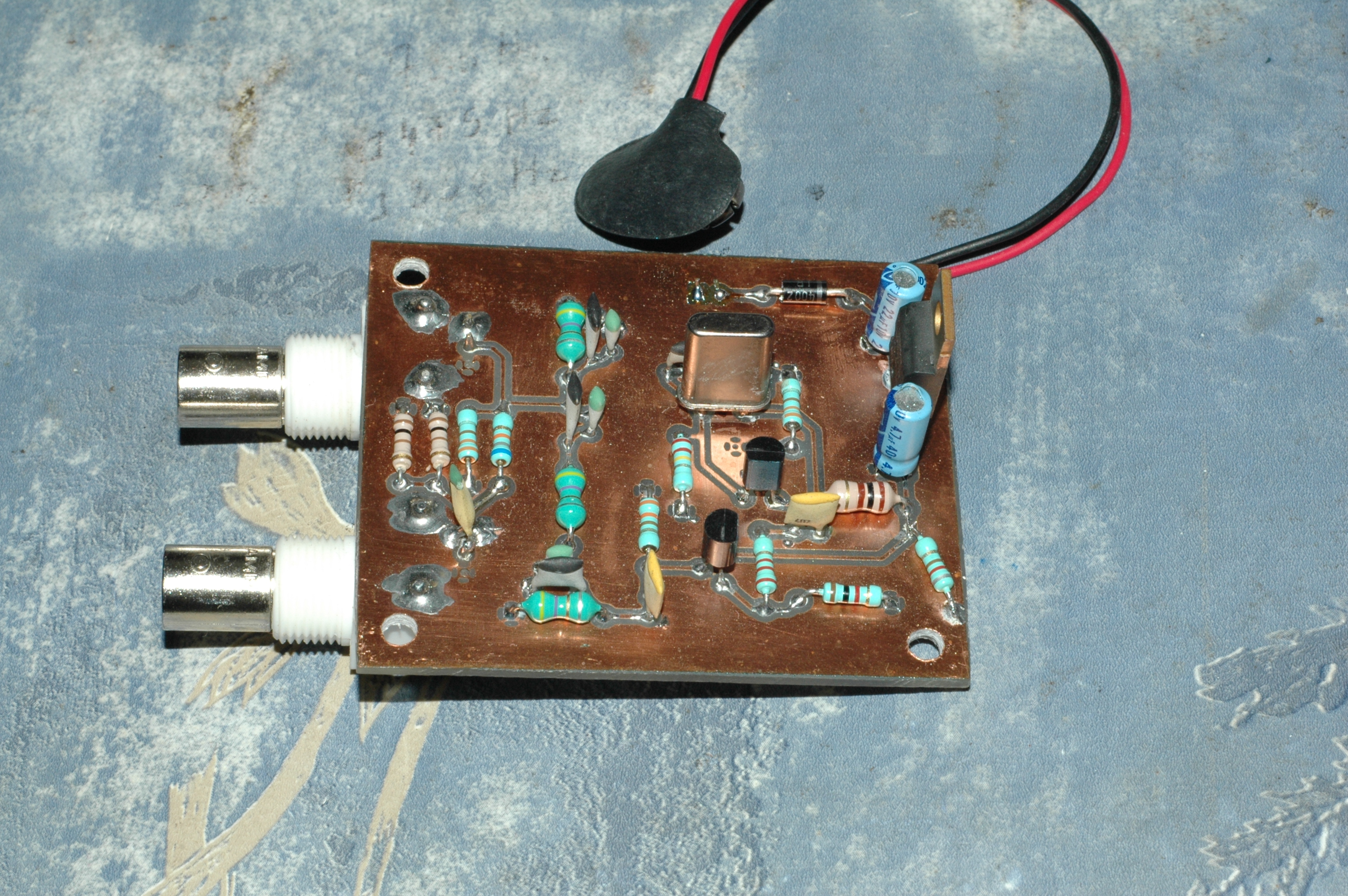
It is at that moment I decided I wanted this on a PCB. I was building a second Peaberry SDR (version 2 had just come out), and I was having some problems with the reception. I didn’t have an RF signal generator, so if I could turn this into a test signal, it could really help me out. The quest became: make something that generates a weak signal so you can directly plug it into the antenna input of a receiver. You can find the schematic of the circuit I came up with here (PDF).
Alright, the only thing remaining was to match the output of the oscillator to 50 Ohm impedance, and attenuate it to a fraction of a millivolt. So how do we determine the output impedance of the oscillator? It turns out this is no simple question. To cover this, I decided to put in a buffer stage (not a bad idea it turns out). A common drain circuit seemed quite interesting: It has a high input impedance (so it will not burden the output of the oscillator a lot, it will act more like a probe), and low output impedance. I assumed that, with a 330 ohm source resistance, I could use this as a ballpark figure of the output impedance of the buffer stage.
Then I added a filter to remove any unwanted harmonics. I don’t know if it does much, actually. I would do it differently right now, and in a few years time I’ll probably do it in yet another way. There’s quite a vast amount of experimenting that can be done on filters alone, it’s not something you can become an expert in overnight. Anyway, I made a pi-filter with resonant LC-circuits at 10MHz, because why not.
The last step is an attenuator. I had seen W2AEW’s video explaining the subject, and made a 60dB attenuator with a 330 Ohm input and 50 Ohm output impedance.
I drew everything with kicad, made a board layout and etched the PCB using the photo-resist method. Unfortunately, I printed the PCB mirrored, and had to mount all the components on the copper side. But in the end, it all worked very nicely. I can tap the signal either before or after the attenuator, this allows me to measure it on a frequency counter. The oscillator frequency turns out to be 10.0039kHz.
There are two things I added after making the board: a resistor to create a minimum load for the 7805 voltage regulator (below a few milli-amps of current, the output voltage is not guaranteed to be correct), and a coupling capacitor after the attenuator (without it, the Peaberry USB device disconnected when I attached the signal source – strange). The circuit has its flaws for sure, but I used it mainly to learn while experimenting, and in that respect it was a great success. Also, it has proven to be much more useful than anticipated: I managed to test the Peaberry SDR with it and get it to work, I have measured the frequency with a rather decent counter and this way I determined that the counter on the Chinese Siglent scope I use at home is accurate. Also, knowing the frequency of the oscillator allows me to check if the receiving frequency of a radio is correct.